lunes, 2 de junio de 2014

Gnuplot background image

Gnuplot can read png binary file and then plot it on the canvas. Using this utility we can add a background image to our plot. Let us see an example script.
reset
set term png
set output "world_population.png"
set multiplot
set xrange [0:799] 
set yrange [0:409]
#As the background picture's size is 800x410,
#we choose xrange and yrange of these values
unset tics
unset border
set lmargin at screen 0.175
set rmargin at screen 0.9
set bmargin at screen 0.15
set tmargin at screen 0.9
#Plot the background image
plot "map.png" binary filetype=png w rgbimage
#The x and y range of the population data file
set xrange [1740:2020]
set yrange [0:7000]
set border
set tics out nomirror scale 2
set mxtics 5
set key left
set xlabel "Year"
set ylabel "Population(in millions)"
plot "population.dat" u 1:2 w lp lw 2 ps 1 pt 7 title "world",\
     "population.dat" u 1:3 w lp lw 2 ps 1 pt 7 title "Africa",\
     "population.dat" u 1:4 w lp lw 2 ps 1 pt 7 title "Asia",\
     "population.dat" u 1:5 w lp lw 2 ps 1 pt 7 title "Europe",\
     "population.dat" u 1:6 w lp lw 2 ps 1 pt 7 title "Katub America",\
     "population.dat" u 1:7 w lp lw 2 ps 1 pt 7 title "Northern America",\
     "population.dat" u 1:8 w lp lw 2 ps 1 pt 7 title "Oceania"
unset multiplot

In this script, map.png is our background image with size 800x410 (That is why we choose xrange and yrange to be 0-799 and 0-409 respectively). population.dat is a file containing information of world population from 0 AD to 2000 AD. The first plot command is used to plot the background image, while the second plot command is used to plot our world population data file. To make these two plot coincide with each other, l,r,t,bmargin are set in the screen coordinate. The data file is as follows:
#Data from http://en.wikipedia.org/wiki/World_population
#Year  World  Africa  Asia  Europe  Latin America  Northern America  Oceania
1750  791  106  502  163  16  2  2  
1800  978  107  635  203  24  7  2  
1850  1262  111  809  276  38  26  2  
1900  1650  133  947  408  74  82  6  
1950  2519  221  1398  547  167  172  12.8  
1955  2756  247  1542  575  191  187  14.3  
1960  2982  277  1674  601  209  204  15.9  
1965  3335  314  1899  634  250  219  17.6  
1970  3692  357  2143  656  285  232  19.4  
1975  4068  408  2397  675  322  243  21.5  
1980  4435  470  2632  692  361  256  22.8  
1985  4831  542  2887  706  401  269  24.7  
1990  5263  622  3168  721  441  283  26.7  
1995  5674  707  3430  727  481  299  28.9  
2000  6070  796  3680  728  520  316  31.0  
2005  6454  888  3917  725  558  332  32.9  
2008  6707  973  4054  732  577  337  34.3

To use background image file of format other than png, we shold first convert it to a png file. This task can be done well using ImageMagick.


At last, this is the picture file world_population.png produced by the plotting script.

Gnuplot background image

miércoles, 28 de marzo de 2012

GNU Plot and SVG: Change the terminal size and font


Again, not really a dev related issue, but I did not find much info online regarding this.

When using gnuplot to create SVG files, one use the set term svg command that sets the following defaults:
gnuplot> set term svg
Terminal type set to 'svg'
Options are 'size 640 480 fixed fname 'Arial' fsize 12 butt '

One can speficy custom parameters to get the desired output:
gnuplot> set term svg size 640,350 fname 'Times New Roman' fsize 10
Terminal type set to 'svg'
Options are 'size 640 350 fixed fname 'Times New Roman' fsize 10 butt '

Demos of palette-mapped 3d terminal: Part 3

Curved line in three dimensions can be drawn by explicitly declaring "set parametric" in splot mode. And here again "pm3d" gifts color map to the line. You can see the scripts by clicking the images.

Flower design
original script (Japanese)


Golfer
The line data was converted from "golfer.ps"
in Ghostscript's examples by using pstoedit.
and slightly modified by hand.
Linux Penguin
The line data was converted from "penguin.eps"
at "Linux 2.0 Penguins" using pstoedit.


Demos of palette-mapped 3d terminal: Part 2

Two dimensional colored contour maps are obtained with "set pm3d map". They sometimes exhibit interesting geometrics. You can see the scripts by clicking each image.


Demos of palette-mapped 3d terminal: Part 1

Pictures in this page were generated by gnuplot's "splot" command with using palette-mapped 3d terminal "pm3d", that have been developed by Dr. Petr Mikukik. You can see the scripts by clicking the pictures. 
Chained tori
One of the most elementary shapes: a sphere.
A kind of Klein's Bottle.
A heart
The "figure-8" form of the Klein bottle
Things like a stool? 
A glass using
"glass.dat" 
A whale in gnuplot's demo (in singular.dem)
The function z(x,y)=-x**3 + 3xy +y**3.
A chart of Mandelbrot set.
It is included gnuplot's demo
(in surface1.dem). 
A chart of Julia set.
See original scripts in Dr. Kono's web site.
A fractal fern.
Hmm... rather looks like tree branch.
A Virtual Seashells -- Natalina
Details: Virtual Seashells
A Virtual Seashells -- Turritella


Equipotential lines


In physics equipotential lines describe lines in space which are at the same potential, for example of the electric field.
Equipotential lines
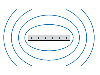
Fig. 1 Equipotential lines of a plate with electric charges (code to produce this figure)
In Fig. 1 equipotential lines for the electric field of six charges equally spaced on a plate are shown. In order to get these lines we need the function of the potential v(x,y) and make a contour plot with splot to a file to save the positions of the lines.
# calculate and save equipotential lines
set view map
unset surface
set contour base
# distance between contour lines according to 1/r
# => equal distance between lines
set cntrparam levels discrete 4,5,6.67,10
set isosam 31,31
set table 'equipotential_lines.txt'
splot v(x,y) w l ls 1
unset table

plot 'equipotential_lines.txt' u 1:2 w l ls 1
The positions of the lines are given by the cntrparam levels which are chosen in a way, to get equally spaced lines in the far field. The set table command stores the contour lines to a file, and finally the last command plots the stored lines.
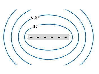
In addition to the equipotential lines the value of the contour is stored as a third column in the equipotential_lines.txt file and can be plotted on the graph, too. This is shown in Fig. 2.
Equipotential lines with labels
Fig. 2 Equipotential lines of a plate with electric charges with labels (code to produce this figure)
To get the label of the contour we have to choose a x-position which is given by lx0 in the following. The labels(x,y) function sets a string to the value of the third column, if the right x-position is given and we are above the plate. The function f(x,y) checks if we are near the point where a label should be drawn and undefines the contour line around this point. The size of this area is given by eps.
lx0 = 1.14899
eps = 0.15
labels(x,y) = (x==lx0 && y>y0) ? stringcolumn(3) : ""
f(x,y) = (abs(lx0-x)<eps && y>y0) ? 1/0 : y

Images within a graph


Suppose you have an image and wanted to add some lines, arrows, a scale or whatever to it. Of course you can do this easily with Gnuplot as you can see in Fig. 1.
jpg image
Fig. 1 Plotting a jpg image within your graph and adding a scale (code to produce this figureimage data). Image source: © SFTEP.
To plot the jpg image of the longnose hawkfish you have to tell the plotcommand that you have binary data, the filetype, and choose rgbimage as a plotting style. Also we ensure that the image axes are in the right relation to each other by setting ratio to -1.
set size ratio -1
plot 'fish.jpg' binary filetype=jpg with rgbimage
The scale needs a little more work, because Gnuplot can not plot a axis with tics to both directions of it. Hence we are using a bunch of arrows to achieve the same result. The text is than set by labels to the axis.
set arrow from 31,40 to 495,40 nohead front ls 1
set for [ii=0:11] arrow from 31+ii*40,35 to 31+ii*40,45 nohead \
   front ls 1
# set number and unit as different labels in order
# to get a smaller distance between them
set label '0'  at  25,57 front tc ls 1
set label 'cm' at  37,57 front tc ls 1
set label '5'  at 225,57 front tc ls 1
set label 'cm' at 237,57 front tc ls 1
set label '10' at 420,57 front tc ls 1
set label 'cm' at 442,57 front tc ls 1
Tags: 
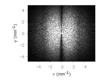
If you have not only some data points or a line to plot but a whole matrix, you could plot its values using different colors as shown in the example plot in Fig. 1. Here a 2D slice of the 3D modulation transfer function of a digital breast tomosynthesis system is presented, thanks to Nicholas Marshall from UZ Gasthuisberg (Leuven) for sharing the data.
Color map
Fig. 1 A simple color map (code to produce this figuredata)
All we need to create such a plot is the image plot style, and of course the data have to be in a proper format. Suppose the following matrix which represents z-values of a measurement.
0 1 2 3 4 3 2 1 0
0 1 2 3 4 3 2 1 0
0 1 2 3 4 3 2 1 0
0 1 2 3 4 3 2 1 0
0 1 2 3 4 3 2 1 0
0 1 2 3 4 3 2 1 0
0 1 2 3 4 3 2 1 0
0 1 2 3 4 3 2 1 0
0 1 2 3 4 3 2 1 0
In order to plot these values in different gray color tones, we specify the corresponding palette. In addition we apply the above mentioned image plot style and the matrix format option. The result is shown in Fig. 2.
set palette grey
plot 'color_map.dat' matrix with image
Fig. 2 A simple color map (code to produce this figuredata)
One remaining problem with Fig. 2 is, that the values on the x- and y-axis are probably not the one which you want, but the corresponding row and column numbers. One way to get the desired values is the use command, which can also be used with image. See Fig. 3 for the result.
plot 'color_map.dat' u (($1-4)/10):2:3 matrix w image
Fig. 3 A color map with a scaled x-axis (code to produce this figuredata)
Another way is to store the axes vectors together with the data. Therefore the data has to be stored as a binary matrix. The format of this matrix has to be the following:
<M>  <y1>   <y2>   <y3>   ... <yN>
<x1> <z1,1> <z1,2> <z1,3> ... <z1,N>
<x2> <z2,1> <z2,2> <z2,3> ... <z2,N>
 :      :      :      :   ...    :
<xM> <zM,1> <zM,2> <zM,3> ... <zM,N>
In Matlab/Octave the binary matrix can be stored using this m-file. The stored binary matrix can then be plotted by adding the binary indicator to the plotcommand.
plot 'color_map.bin' binary matrix with image
Note that in principle a color map can also be created by the splot command:
set pm3d map
splot 'data.dat' matrix
But if you create vector graphics with this command you will get a really big output file, because every single point will be drawn separately. For example check the graph from Fig. 1 as pdf created with plot and image and as pdf created with splot and pm3d map.